Prototyping | 3D Printing | Solidworks | Meshmixer
Custom Fitted Splints
Developed a method to create a custom splint for any patient using a smartphone, CAD software, and a 3D printer. Engaged in the review stage of the rapid prototyping process. Next project phases will tackle design for user comfort, failure analysis, and automation of splint model generation.(Dec 2023 - Present)
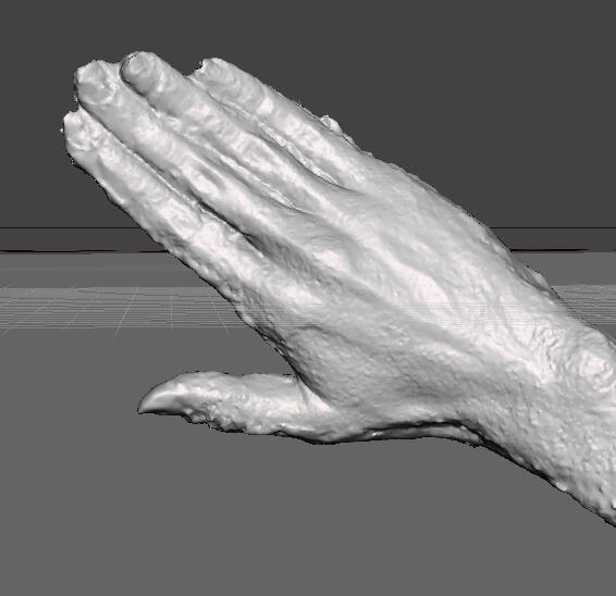
1. Raw Scan
A patient uses their smartphone to take photos using the Kiri Engine app. It will stitch these photos into a 3D scan of the injured body part. The patient then sends the scan.
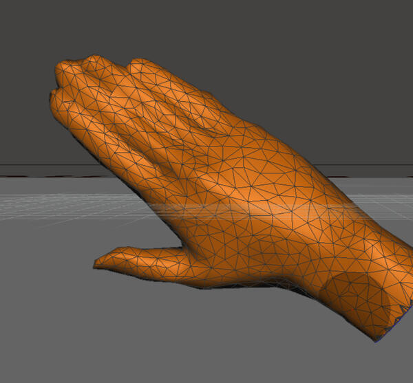
2. Refined Scan
The patients 3D scan was then refined using Meshmixer to reduce file size and noise. This step is critical to produce a usable scan prior to modeling the splint.
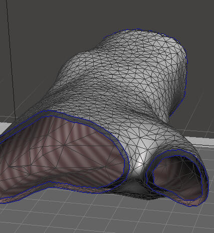
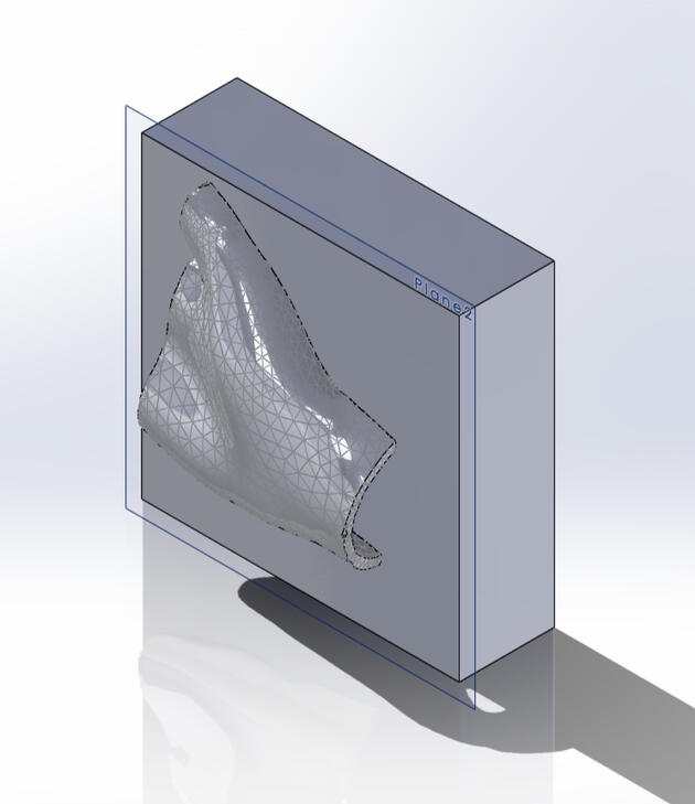
3. Offset Generation
A surface is generated at an offset of 4mm from the patients scan. Meshmixer is used to fill the gaps between the surfaces and create a solid body for export.
4. Import to Solidworks
The file is imported to Solidworks and the splint is split in two pieces to produce a clamshell design.
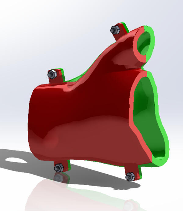
5. Locking Mechanism
A simple mechanism is added to allow the splint to be secured on the patient.
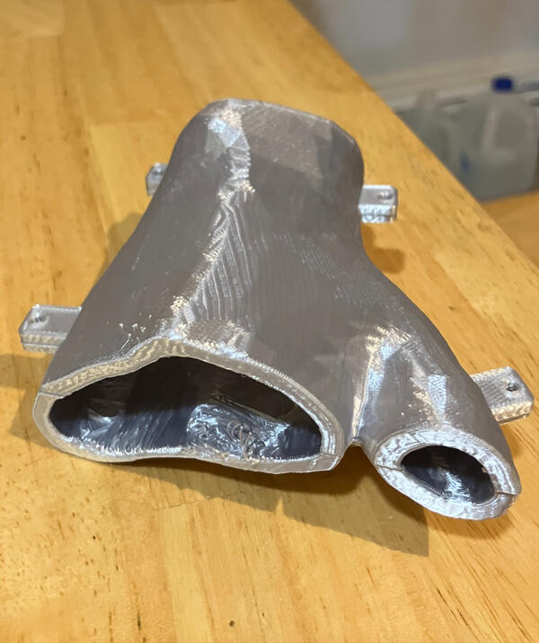
6. Splint V1
The splint is printed and ready for wear in roughly 9 hours. Further refinement of the splint design will result in shorter wait times.
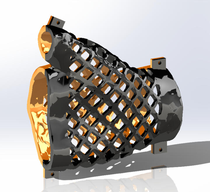
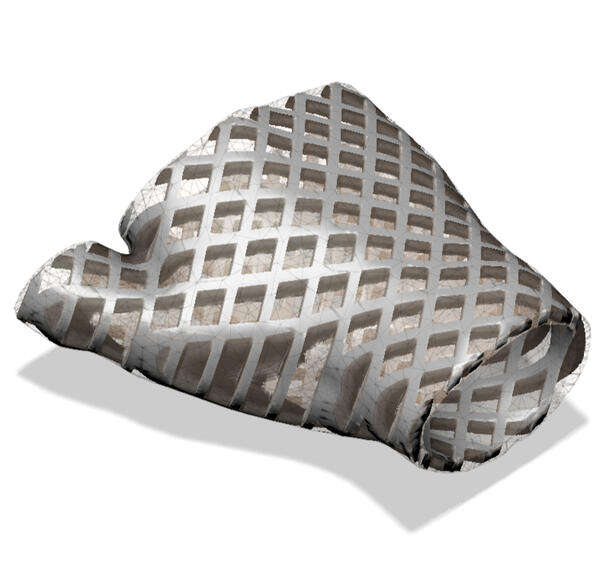
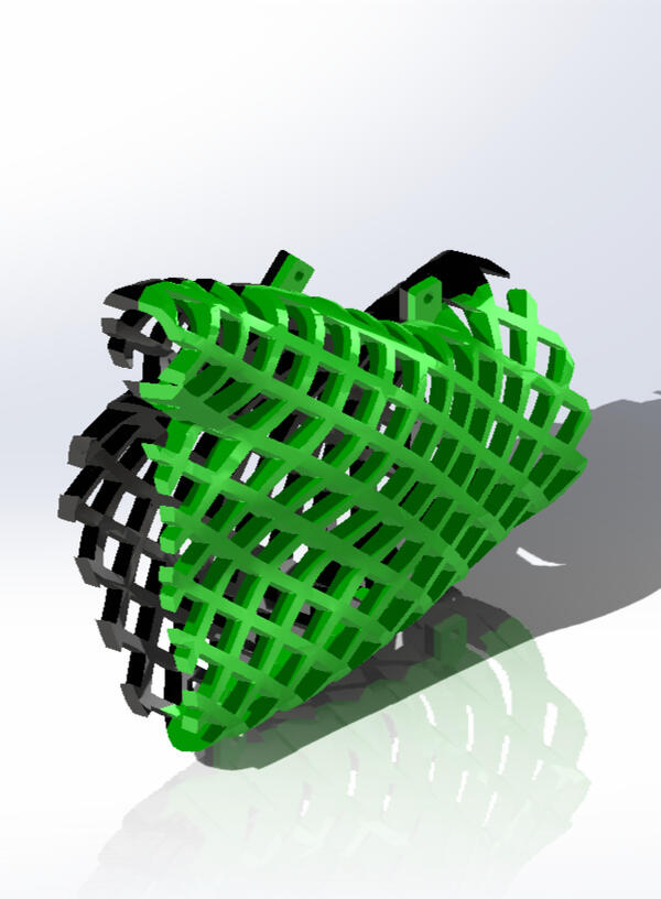
7. Lattice Generation
To increase breathability and retain structural strength Fusion 360 was utilized to generate lattice.Lattice results in faster print times and less material cost. This design was only 25% of the material when compared to the initial design.The main concerns with the second prototype are print quality and comfort. the edges of the splint will likely need to be addressed as they currently have edges that could prove uncomfortable to the patient.
8. 2.5D X-Cell Lattice
The X-Cell Lattice above was favored for the lack of sharp features on the inside of the splint.
9. Splint V2
With the lattice concept proved in Solidworks I decided to further refine the model prior to printing.
10. Edge Removal
To further increase user comfort and safety I added a solid band towards the fingers and wrist.I noticed while modeling the second prototype that there were sharp edges towards the fingers and wrist. I could tell this would likely cause the patient discomfort and could even have the potential to cut them.The full time to print for this version of the splint was 42 hours.
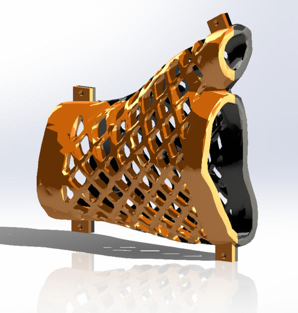
11. CAD Rendering
12. Splint V3
13. Initial Testing
During the first wear study I learned that the splint is good at restricting movement of the hand. This is great since the hand will need to remain steady while it is recovering from injury.I also recommend sanding the interior edges of the seams where each half meets. This reduces sharp areas that can dig into the hand.I will adjust the size of the splint and print both halves with supports on the outside face for user comfort.With these improvements I plan to conduct a longer wear study, first an hour, then a few hours, and then a day.
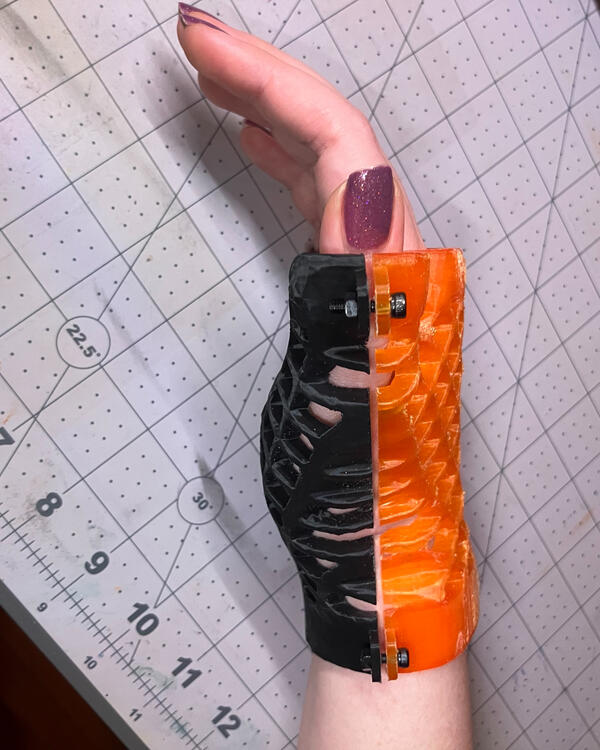
14. Tight Fit
The current version is a bit too tight. I plan to offset the splint geometry by 4mm to accommodate.
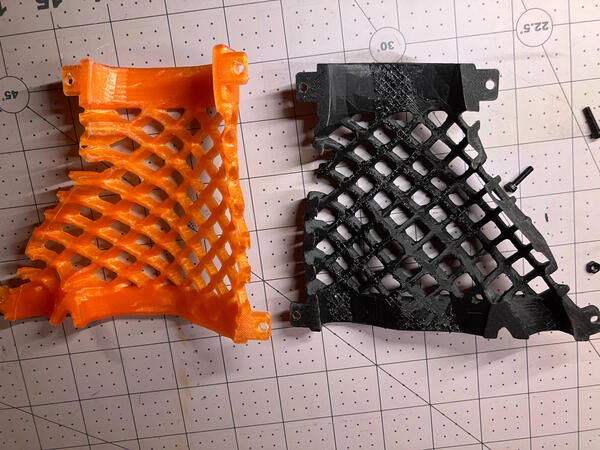
15. Support Settings
The black half was printed with supports on the inside face causing a rough interior - not ideal for wear.